This content originally appeared on Level Up Coding – Medium and was authored by Wadix Technologies

1. Introduction:
The CPU is the fastest and most impatient component in a system. Its nightmare? Waiting for memory. Accessing memory is a painful journey for the CPU — riddled with latency, bus contention, and arbitration delays caused by other masters sharing the interconnect. Left to its own desires, the CPU would prefer everything to happen at its own internal clock speed without interruptions.
To close this performance gap, designers have long sought ways to shortcut the memory access path. Caches are one such solution — but they introduce unpredictability. For real-time systems that demand deterministic behavior, this isn’t acceptable. That’s where Tightly Coupled Memory (TCM) comes in.
2. What Is a TCM?
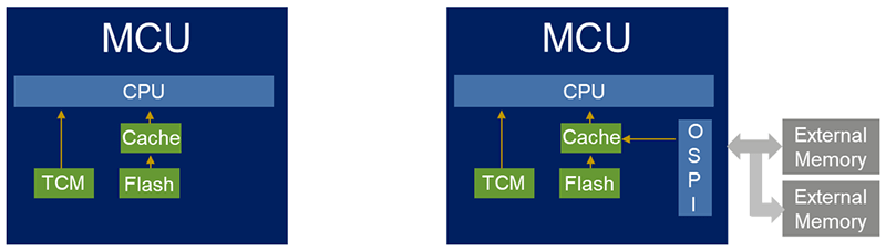
Tightly Coupled Memory (TCM) is a block of SRAM directly attached to the CPU. Unlike regular memory, which sits on a shared system bus alongside peripherals and other memory regions, TCM has dedicated buses that connect it straight to the processor core. This direct connection eliminates contention and arbitration delays, making TCM what is often called a zero wait state memory.
There are typically two types of TCMs:
· ITCM (Instruction TCM) — used for instruction fetches
· DTCM (Data TCM) — used for data access
Because TCMs bypass the main system interconnect and do not compete with other bus masters, the CPU can access them immediately, without being stalled .
But TCM isn’t just about raw speed — it offers something even more critical for real-time systems: determinism.
Access times are fixed and predictable, which is essential for systems that require consistent timing behavior.
Arm cortex m7 block diagram:

Behind the scenes, TCM is just SRAM, but it’s mapped to a special region in the processor’s address space. Accessing that region automatically triggers a direct path to the TCM hardware.
3. How to use TCM memory:
Using TCMs in your embedded application begins with understanding how your microcontroller maps these memory regions. In most MCUs that support TCM — such as ARM Cortex-M7 — ITCM and DTCM are mapped to fixed address regions, separate from regular RAM or flash. To take advantage of TCM, you need to manually place critical code and data into these regions, usually by modifying your linker script.
On STM32H7 devices, the ITCM is typically mapped at 0x00000000 and DTCM at 0x20000000. In your linker script, you might define a memory region like:
ITCMRAM (xrw) : ORIGIN = 0x00000000, LENGTH = 64K
DTCMRAM (xrw) : ORIGIN = 0x20000000, LENGTH = 128K
__attribute__((section(".itcm"))) void fast_function(void)
{
  /* code here*/
}
__attribute__((section(".dtcm"))) uint8_t buffer[256];
4. Flash vs ITCM: A Simple Benchmark Test
To demonstrate how much faster ITCM is compared to flash, we created a simple test that runs the same sequence of instructions from two different locations: once from flash, and once from ITCM.
To run a function from ITCM, we first need to make sure the build system knows where to place it and that it actually gets copied to ITCM at startup. This involves two small changes: one in the linker script, and one in the startup code.
We create a new section called .itcmtext in the linker script and map it to the ITCM memory region (address 0x00000000 on STM32H7).


At reset, before main() runs, we copy the .itcmtext section from flash to ITCM using the _siitcm, _sitcm, and _eitcm symbols defined in the linker script.

The idea of the benchmark:
· We write two functions that do nothing but execute a fixed number of NOP (no operation) instructions inside a loop.
· The flash version is stored in normal program flash memory (0x08000000).
· The ITCM version is placed in the ITCM memory region (0x00000000) so the CPU fetches it directly with zero wait states.
· We use the CPU’s DWT cycle counter to measure how many clock cycles each version takes to run.
Because both functions contain the exact same instructions, any difference in execution time is purely due to the instruction fetch speed of flash vs ITCM.
the benchmark code is:
void loop_flash(uint32_t n)
{
  while (n - )
  {
    __asm volatile(
    "nop\n""nop\n""nop\n""nop\n""nop\n""nop\n""nop\n""nop\n"
    "nop\n""nop\n""nop\n""nop\n""nop\n""nop\n""nop\n""nop\n"
    "nop\n""nop\n""nop\n""nop\n""nop\n""nop\n""nop\n""nop\n"
    "nop\n""nop\n""nop\n""nop\n""nop\n""nop\n""nop\n""nop\n"
    "nop\n""nop\n""nop\n""nop\n""nop\n""nop\n""nop\n""nop\n"
  );
 }
}

/* ITCM function */
__attribute__((noinline, section(".itcmtext")))
void loop_itcm(uint32_t n)
{
  while (n - )
  {
  __asm volatile(
    "nop\n""nop\n""nop\n""nop\n""nop\n""nop\n""nop\n""nop\n"
    "nop\n""nop\n""nop\n""nop\n""nop\n""nop\n""nop\n""nop\n"
    "nop\n""nop\n""nop\n""nop\n""nop\n""nop\n""nop\n""nop\n"
    "nop\n""nop\n""nop\n""nop\n""nop\n""nop\n""nop\n""nop\n"
    "nop\n""nop\n""nop\n""nop\n""nop\n""nop\n""nop\n""nop\n"
    );
  }
}

int main(void)
{
  /* I-Cache - - - - - - - - - - - - - - - - - - - - - - - - - - - - -*/
  #undef ENABLE_ICACHE
  #ifdef ENABLE_ICACHE
  SCB_EnableICache();
  #endif /*ENABLE_ICACHE*/
  /* MCU Configuration - - - - - - - - - - - - - - - - - - - - - - - - - - - - */
  HAL_Init();
  SystemClock_Config();
  uint32_t iterations = 200000;
  volatile uint32_t cycles_itcm = 0U ;
  volatile uint32_t cycles_flash =0U;
  /* Enable DWT cycle counter */
  CoreDebug->DEMCR |= CoreDebug_DEMCR_TRCENA_Msk;
  DWT->CYCCNT = 0;
  DWT->CTRL |= DWT_CTRL_CYCCNTENA_Msk;
  /* - - Measure Flash - - */
  DWT->CYCCNT = 0;
  loop_flash( iterations );
  cycles_flash = DWT->CYCCNT;
  /* - - Measure ITCM - - */
  DWT->CYCCNT = 0;
  loop_itcm( iterations );
  cycles_itcm = DWT->CYCCNT ;
  while (1)
  {
  /*infinit loop*/
  }
}
The ITCM run completes much faster:
If we enable the instruction cache, the performance gap between flash and ITCM becomes much smaller. In many cases, cached flash fetches can approach ITCM speeds for sequential code.
However, ITCM is not just about speed — it’s about determinism. Instruction cache performance depends on whether the needed instructions are already in the cache. A cache miss can suddenly add multiple wait states, introducing unpredictable timing. In contrast, a function in ITCM is fetched directly from tightly coupled memory, so the access time is always the same — every single time.
It’s technically possible to configure flash with zero wait states to match ITCM speed, but this usually means lowering the system clock to meet flash timing requirements. That’s a big performance trade-off for the whole system.
For applications that need both performance and guaranteed timing, ITCM offers the best of both worlds: instructions execute at full CPU speed with zero wait states and fully predictable fetch times, no matter the bus load or code path.
5. Examples of Using TCM Memories:
TCM memories really shine when you use them for the parts of your application that can’t afford to wait. For example, putting interrupt service routines in ITCM means the CPU can jump in and handle events immediately. On the data side, DTCM is perfect for latency-sensitive buffers, like the ones used by high-speed ADC or DAC DMA transfers, because it avoids the bus contention that happens in shared SRAM. Signal-processing tasks such as FFTs or FIR filters also benefit from having the code in ITCM and the working data in DTCM, giving maximum throughput.
In safety-critical systems this deterministic behavior can be the difference between meeting and missing a deadline.
6. Conclusion:
TCM memories give the CPU a direct, predictable path to the code and data that matter most. By combining zero wait-state speed with guaranteed timing, they become a reliable way to meet the strict performance demands of real-time embedded systems.
If you enjoyed this article, please make sure to Subscribe, Clap, Comment and Check out our online courses today!
TCM Memories: Zero Wait-State Speed and Determinism was originally published in Level Up Coding on Medium, where people are continuing the conversation by highlighting and responding to this story.
This content originally appeared on Level Up Coding – Medium and was authored by Wadix Technologies